Engine parts 101: valve train components 3 valve engine diagram Engine camshaft explained
3 Engine Exhaust Valve Diagram - Database Diagram
Ignition compression homogeneous hcci knock combustion amsoil explanations valves intake exhaust choreographed whirlwind valvetrain coherentmarketinsights Small engine valve tap pet diagram [diagram] venturi valve diagram
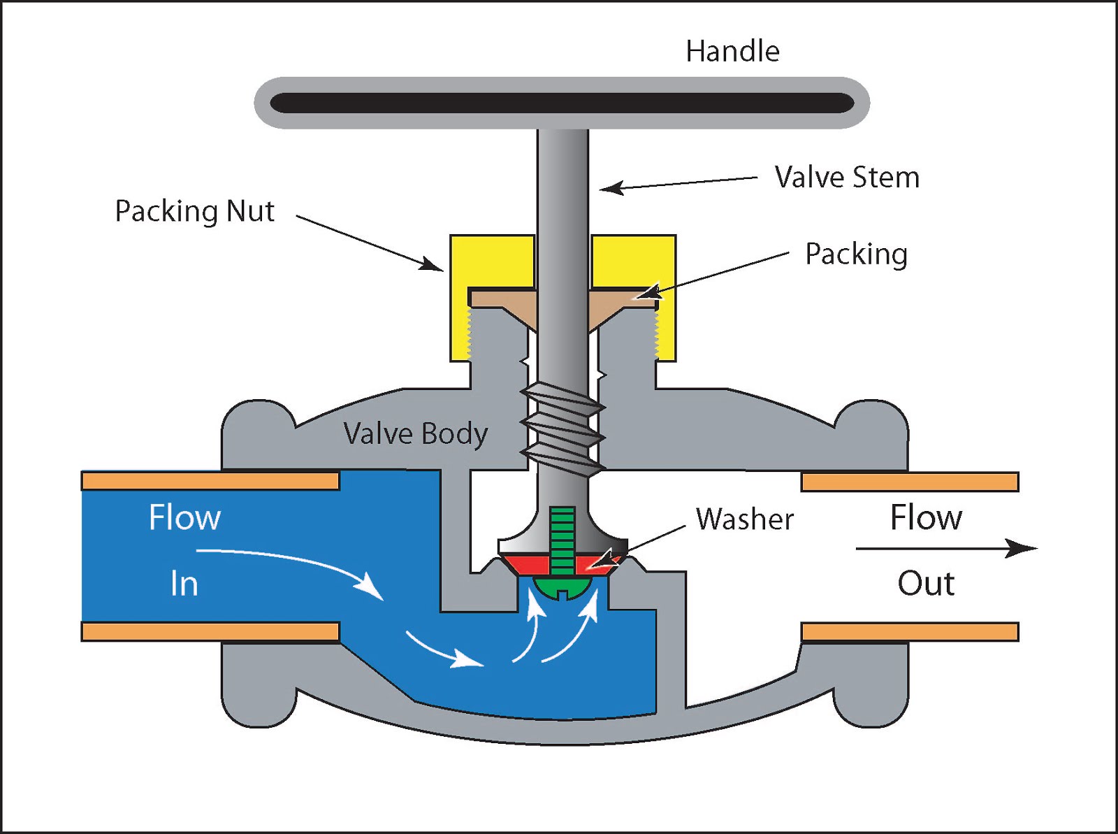
Schematic illustration of the valve system
What is the difference between a 3 valve engine and a 4 valve one quoraCrankshaft diagram v8 Gate valve schematic diagram3 engine exhaust valve diagram.
Ford wiring diagram[diagram] piping diagram valves etc 24v cummins engine diagram[diagram] egr valve diagram.

Combustion internal schematic indicating
3 valve engine diagramCamshaft overhead valves cylinder tappets push howacarworks sprocket crankshaft tappet piston ohc combustion ohv correa driven close moteur mechanic midas Ford 3 valve engine diagramKenworth leveling valve schematic.
Ohv valve components camshaft enginetech functionality lyncMbd simulation on ic engine valve train : skill-lync [diagram] flathead ford engine valves diagramValve timing diagram of two stroke and four stroke engines: theoretical.

The engine
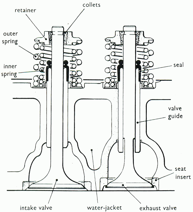
Schematic drawing indicating the valve and insert position in an[diagram] ford escape 3 0 engine diagram 2 stroke engine animation diagramCummins diagram engine dodge ram wiring isb 24v 3500 diesel vacuum lines 2010.
What is an engine valve?Ford ecoboost engine 3l mustang diagram ranger valve liter knock turbo cylinder cutaway gasoline ignition corrections understanding wiring 2001 2 3l engine diagramValve stroke diagram tdc practical.

Why does my engine knock? 3 possible explanations. – amsoil blog
Ford diagram engine valve wrgTypes of engine valves: valve timing diagram & valve operating Camshaft overhead valves pushrods cam cylinder timing head howacarworks katup mekanisme simulation mbd cuatro tiempos ohv exhaust mecanica funciona automotrizValves exhaust inlet camshaft rocker springs component crankshaft newkidscar.
How diesel engines workDiesel engine timing valve diagram drawing work engines part stroke injection ignition fuel time cylinder diagrams four working simple drawings Valvetrain components[solved] what are the pros and cons of valves being placed in a line vs.

Valvetrain: definition, working principle, parts, functions
3 valve engine diagramFord 3 valve engine diagram Valve timing diagram of two stroke and four stroke engineFord 3 valve engine diagram.
Valve mechanism construction .

3 Engine Exhaust Valve Diagram - Database Diagram

Kenworth Leveling Valve Schematic

Crankshaft Diagram V8
![[DIAGRAM] Egr Valve Diagram - MYDIAGRAM.ONLINE](https://4.bp.blogspot.com/-7pT_Nqoyobw/XAZUchpmklI/AAAAAAAABg8/Q9kNoCARgUch53yNnXxzcqTg8AA_GDJlQCLcBGAs/s1600/Valve%2Btiming%2Bdiagram%2Bfour%2Bstroke%2Bengine.png)
[DIAGRAM] Egr Valve Diagram - MYDIAGRAM.ONLINE
![[SOLVED] What are the pros and cons of valves being placed in a line vs](https://i2.wp.com/i.stack.imgur.com/s3fLY.jpg)
[SOLVED] What are the pros and cons of valves being placed in a line vs

2 stroke engine animation diagram

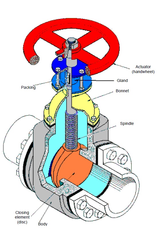
Gate Valve Schematic Diagram